Spacer Damper (Twin)
Spacer Damper (Twin)
MM Powerline Transmission specializes in providing premium accessories designed to optimize the performance and safety of electrical conductors across diverse applications. Our extensive product range is engineered with precision to not only meet industry standards but also exceed the expectations of our customers.
Twin Spacer Dampers
Twin spacer dampers represent an innovative solution aimed at enhancing the stability and reliability of high voltage transmission lines, critical for ensuring uninterrupted electricity supply over long distances. These dampers play a pivotal role in mitigating dynamic forces and vibrations that could compromise the structural integrity of transmission towers and lines, particularly in challenging environmental conditions.
Importance in High Voltage Lines
- Vibration Control: High voltage transmission lines are susceptible to various vibrations, including aeolian (wind-induced) vibrations and galloping, which can lead to fatigue failure of conductors, insulators, and supporting structures. Twin spacer dampers are strategically positioned along the transmission line to absorb and dissipate vibrational energy, thereby reducing oscillations and minimizing the risk of damage.
- Enhanced Stability: By effectively controlling vibrations, twin spacer dampers improve the overall stability of the transmission line. This is crucial for maintaining the mechanical integrity of the line under dynamic loads caused by wind gusts, ice accumulation, and electromagnetic forces.
- Extended Lifespan: Dampers contribute to extending the operational lifespan of transmission infrastructure by reducing stress concentrations and fatigue cycles on critical components. This enhances the reliability of the power grid and decreases long-term maintenance costs.
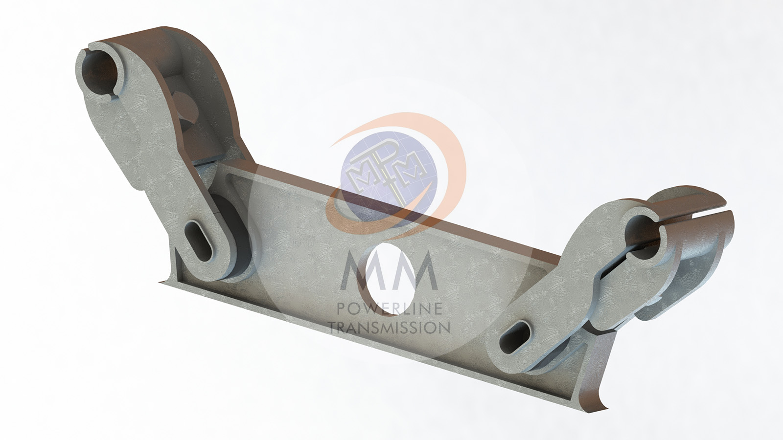
Design and Functionality
- Dual Damping Units: Twin spacer dampers feature two damping units strategically spaced along the conductor span. Each unit is designed to independently absorb and dissipate vibrational energy, effectively reducing oscillation amplitudes.
- Spacer Configuration: Spacers between damping units play a crucial role in adjusting the natural frequency of the damper system. This allows for fine-tuning of damping characteristics to match specific environmental conditions and operational requirements.
- Materials and Durability: Constructed from high-strength materials such as composite polymers or metals, twin spacer dampers are engineered to withstand harsh environmental conditions, including UV exposure, temperature variations, and mechanical stresses.
Applications and Benefits
- Long-Span Lines: Ideal for extra-high voltage (EHV) and ultra-high voltage (UHV) transmission lines where long spans between towers increase susceptibility to vibrations.
- Versatility: Effective across diverse geographical and climatic conditions, from coastal regions prone to high winds to mountainous terrains experiencing variable weather patterns.
- Cost Efficiency: While initial installation costs may be higher compared to conventional methods, the long-term benefits include reduced maintenance expenses and minimized downtime, resulting in overall cost savings.
At MM Powerline Transmission, we are dedicated to delivering advanced solutions that safeguard infrastructure and optimize electrical transmission efficiency. Contact us to learn more about how our twin spacer dampers and other conductor accessories can enhance the performance of your next project.
BOQ
| SL. NO | DESCRIPTION | MATERIAL | QTY./SET |
|---|---|---|---|
|
1 |
CENTRAL BODY
|
ALUMINIUM ALLOY
|
1 NOS |
|
2 |
CLAMP BODY
|
ALUMINIUM ALLOY
|
2 NOS |
|
3 |
CLAMP KEEPER
|
ALUMINIUM ALLOY
|
2 NOS |
|
4 |
OVAL TUBE
|
ALUMINIUM ALLOY
|
2 NOS |
|
5 |
BUSH
|
ELASTOMER RUBBER
|
4 NOS |
|
6 |
HEX BOLT & NUT M12
|
MILD STEEL, HDG
|
2 NOS |
|
7 |
PLAIN WASHER M12
|
MILD STEEL, HDG
|
2 NOS |
|
8 |
SPRING WASHER M12
|
SPRING STEEL, HDG
|
2 NOS |
TECHNICAL DATA
- GENERAL TOLERANCE: ±5% UNLESS OTHERWISE SPECIFIED.
- MIN. CORONA EXTINCTION VOLTAGE (DRY) : 320 KV. (RMS.)
- RIV AT 1 MHZ 305 KV (RMS) BELOW 1000 MICROVOLTS.
- COMPRESSION LOAD : 15KN & TENSION LOAD : 7.5 KN.
- CLAMP SLIP STRENGTH
- BEFORE FATIGUE TEST : 6.5 KN.
- AFTER FATIGUE TEST : 5.2 KN.
- MAGNETIC POWER LOSS PER SPACER AT 800 AMP. 50 Hz MAX. 1 WATT.
- INSTALLATION TORQUE : 45Nm.
Other Product Quick Link
AVAILABLE FOR THE FOLLOWING CONDUCTORS
For ACSR
| SL. NO | ACSR CODE | CONDUCTOR DIA. |
|---|---|---|
|
1 |
RACCOON |
12.27 |
|
2 |
DOG |
14.15 |
|
3 |
LEOPARD |
15.84 |
|
4 |
COYOTE |
15.86 |
|
5 |
TIGER |
16.52 |
|
6 |
WOLF |
18.13 |
|
7 |
ORIOLE |
18.82 |
|
8 |
LYNX |
19.53 |
|
9 |
LARK |
20.47 |
|
10 |
PANTHER |
21.00 |
|
11 |
LION |
22.26 |
|
12 |
BEAR |
23.45 |
|
13 |
GROSBEAK |
25.16 |
|
14 |
TEAL |
25.24 |
|
15 |
GOAT |
25.97 |
|
16 |
ANTELOPE |
26.73 |
|
17 |
KUNDAH |
26.80 |
|
18 |
SHEEP |
27.93 |
|
19 |
DRAKE |
28.14 |
|
20 |
ZEBRA |
28.62 |
|
21 |
DEER |
29.89 |
|
22 |
CAMEL |
30.15 |
|
23 |
ELK |
31.50 |
|
24 |
MORKULLA |
31.68 |
|
25 |
MOOSE |
31.77 |
|
26 |
BERSIMIS |
35.05 |
For AAAC
| SL. NO | AAAC CODE | CONDUCTOR DIA. |
|---|---|---|
|
1 |
RABBIT |
9.30 |
|
2 |
DOG |
12.78 |
|
3 |
PANTHER |
19.70 |
|
4 |
PANTHER-UP |
22.05 |
|
5 |
YEW |
25.97 |
|
6 |
ZEBRA |
28.00 |
|
7 |
ZEBRA-UP |
29.79 |